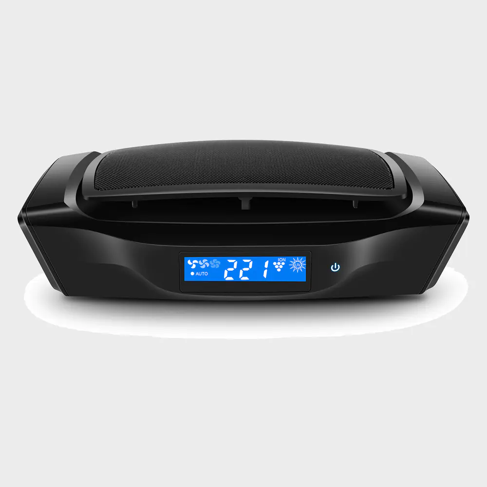
Build your own Micromill and prepare the spirit at home.
Micromill is a home appliance for preparing spirits.
Design and software can be found in this description.
The list of materials has been added as an attachment.
View the video to see the Micromill running.
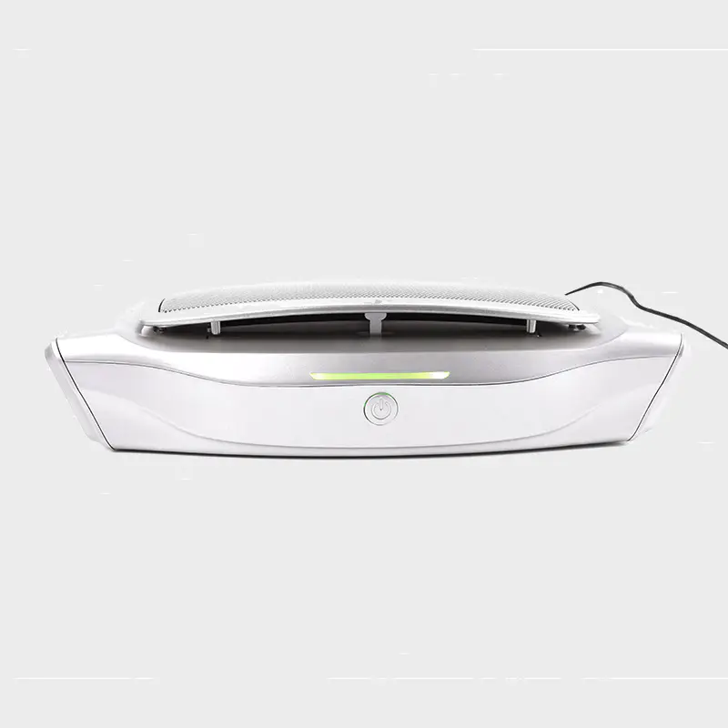
This housing acts as a support and housing for the control unit and the pump.
The main part of the housing is an electrical housing made of ABS plastic.
The housing is equipped with rubber seals with four screws and covers. 1.
Insert the seal into the cover.
Cut off the extra seal. 2.
The cover will be used as a stand.
Put the lid away.
Pour the shell over.
This will be the most important thing.
Four holes need to be drilled at the top.
See pdf for more information. 3.
Measure and mark the position of the four holes. 4.
The first two holes are 8mm.
For this I used the lip and the thorn drill. 5.
The third hole is 16mm and the last one is 25mm.
For this I used an adjustable wood drill bit. 6.
After drilling, use half-round rasp.
Next is the front of the case.
Holes in the switch need to be drilled. 7.
Measure and mark the position of the four holes. 8.
Drill four holes 16mm.
For this I used an adjustable wood drill bit. 9.
After drilling, use half-round rasp.
Next is the left side of the box.
Two holes need to be drilled for cable joints. 10.
Measure and mark the position of the four holes. 11.
Drill four holes 16mm.
For this I used an adjustable wood drill bit. 12.
After drilling, use half-round rasp.
After the drilling is completed, insert the cable gland.
Then install the pipe clamp.
There will be larger pipe clamps in the box.
It will keep the pump later.
Inside and outside the shell there is a Fender gasket to support the plastic.
There will be a smaller pipe clamp at the top to fix the column pipe.
The third pipe clamp will be installed in the hole on the right.
First, I installed the bolts with two Fender washers and two hex nuts.
Then I install the second pipe clip on the top.
It will hold the cooler tube.
Module 1, case completion!
The pipe consists of two parts: the cooler and the column.
Both are welded by copper tubes and fittings.
See pdf drawing for parts list and design.
I am using the sn97 cu3 lead as welding-
Free welding for drinking water.
As flux, I use flux (SN97Cu3)
Contains paste.
Start with column. 1.
Pipe and fittings required to assemble the column.
Check all parts are in place. 2.
Apply the solder paste to all connections and assemble the column.
Make sure all connections are aligned. 3.
Welding column. Let cool down.
Prepare for the cooler. Heat exchanger--
Inner tube 12mm. 4. Slide tee-
12mm workpiece and Reducer on pipe.
These will be welded in step 10. 5.
Apply the solder to the past and assemble the pipe with two reducers. 6.
Weld the two reducers to the inner tube. Let cool down. Heat exchanger--
Outer tube 18mm. 7.
Sliding table and teepiece (step 4)
To the end of the 12mm pipe. 8.
Slide Over 18mm pipe and second tee
One piece from the other end. 9.
Slide on the reducer to close the housing of the cooler.
Add tin paste when assembling. 10.
Welded outer pipe. Let cool down.
Note: There may be a plug inside the reducer that closes the outer tube.
In order for it to go through the smaller reducer, it needs to be deleted using a file. The inlet pipe. 11.
Assemble pipes, bows and reducers with welding past. 12. Solder. Let cool down. Outlet pipe. 13.
Assemble the bow, tube and 45 degree bow with welding past. 14. Solder. Let cool down. The cooler. 15.
Assemble the cooler from the heat exchanger, inlet and outlet pipes. 16.
Add the welding past on the inlet and outlet fittings. 17.
Assemble three pieces. 18. Solder. Let cool down.
Excess flux and debris need to be removed after welding.
Dip the water column and cooler into the water (e. g. bucket)for one hour.
Then rinse with water.
Dry and polish the outside with a cloth.
The module is powered by a pump and a ground cable (see drawing). 1.
Peel off the insulation material with a length of 5mm from the core. 2.
Connect the blade connector to 2-wire cables. 3. Connect 2-
Wire and Cable for pump. 4.
Connect the ring connector to the ring terminal.
Connection of pipes as different modules (see drawing). 1.
Prepare the pipe of the specified length. 2.
Assemble tubing according to drawings. 3.
Add hose clamps according to drawings.
The heater consists of a cardridge heater, 2-
Wire and Cable and hot switch (
120 C, normally closed)(see drawing).
Heater heart through 2-wire cable.
If the temperature of the hot switch is higher than 120 °c, the switch is on and the heater is off. 1.
Peel off the insulation material from the core in a length of 5mm. 2.
Weld a wire of the Heat switch to a wire in the heart of the heater. 3.
Weld the other wire of the heater to one wire of the cable. 4.
Weld the other wire of the cable to the other wire of the thermal switch. 5.
Cover solder joints with schink pipes for insulation.
Arduino modules are shielded by Arduino and Arduino (see drawing).
Arduino will be used as is.
The writing of Module 6 focuses on the writing of shielding.
The purpose of the shield is to provide sockets for other modules.
Other modules are connected to the Arduino through these sockets.
The prototype shield is the foundation of the shield.
For more information about connections, see drawing. 1.
Weld all outlets to the prototype shield. 2.
Welding resistance. 3.
Weld all connections from pins to sockets. 4.
Weld all connections of GND and 5 v to the socket. 5.
Test the connection.
Power supply has two functions.
First, it receives power from the power grid (110-240 VAC)
And convert Arduino to 5 VDC.
The second relay switches the heater and the pump.
The modules have relays and power converters.
The power supply then installs the modules on the PCB and connects them according to the drawings. 1.
Remove the screw terminals from the two relay modules and put them on one side. 2.
Welding control cable for relay module.
As shown in the figure, weld the pins to the other end of the cable and use the Shrink tube to be insulated. 4.
Mark a pin with a permanent mark. 5.
Solder the module to the PCB. 6. Solder AC-
DC converter to PCB. 7.
PCB welding screw terminals. 8.
Connect screw terminals, relays, and converters as shown in the figure. 9.
Weld the USB cable to the converter.
Two temperature sensors are prepared (see drawing). 1. Prepare cables. 2.
Solder the pins onto the cable using a Shrink tube and insulated. 3.
As shown in the figure, weld the cable to the temperature sensor and use the Shrink tube to be insulated. 4.
Mark a pin with a permanent mark.
After assembling the sensor, you need to read out the address of the sensor.
Connect Arduino (with shield)
To the first sensor and run the address program (
See get_temp_address _ ver0. 1. pdf).
Note the notes on each sensor.
A specific address needs to be included in the microkill program (Microstill_ver0. 2. pdf).
Four buttons are needed (see drawing). 1. Prepare cables. 2.
Welding needle on cable. 3.
As shown in the figure, weld the cable to the button and use the Shrink tube to be insulated. 4.
Mark a pin with a permanent mark. 1.
Packing of columns: Loose packing with copper mesh along the whole column.
Make sure the mesh is evenly distributed from bottom to top.
Intensive packaging at export.
Plug in the copper mesh at the socket and push firmly into ellbow. 2.
Install the heater on the post: wrap the foil around colum (2 turns).
Wrap the foil around the column and heater.
The packaging temperature switch under the last tin foil.
Fix the heater on the column using three hose clamps. 3.
Install the column and cooler at the chassis. 4.
Install tubing at column and cooler: install elbow on top of column.
Install tubing between column and cooler. 1.
Installation pump: installation tube for cooler inlet.
Connect the tube to the outlet of the pump.
Install the inlet tube to the pump.
Install the inlet tube on the cable gland.
Install the pump in the pipe clamp. 2.
Installation button: remove the white button and remove the nut and Fender from the thread.
Through the Wire in front of the box through the respective whole.
Insert the button into the whole and fix it with a Fender and nut.
Continue using other buttons. 3.
Install the temperature sensor using copper wire: install the temperature sensor on the cooler.
Select a position on the side of the tee-piece.
Install the temperature sensor at the column.
Select the position opposite the tin foil packaging top to heat the heart shape.
Pass the sensor wire through the cable gland at the top of the case.
Wire the heater through the cable gland at the top of the case. 8.
Install arduino: Include the sensor address in the code (see step 8)
Upload the program to arduino.
Installation shield on Arduino.
Connect the button to the shield.
Connect the sensor to the shield.
Connect the power supply to the shield and arduino board (
2 x relay and USB cable).
Install arduino just in case. 9.
Install the power supply: plug the power cord into the cable gland.
Connect the power cord to the power supply.
Connect the pump to the power supply.
Connect the heater to the power supply.
Install the power supply just in case. 10. Close case.